

『Oil Flow Meter for Hazardous Area: Class 1 Div 1 System Grounding Guidelines』Related information(flow rotameter|digital flow meter|balo meter|hydraulic flow meter|volumetric meter|positive displacement meter|pitot tube flow meter|displacement meter|cfm meter|variable area flow meter|inline flow meter|differential pressure flow meter|calibrated flow meter|velocity meter|paddle wheel flow meter|oval gear flow meter|anemometer hvac|multiphase flow meter|doppler flow meter|thorpe tube flowmeter|heat flow meter)
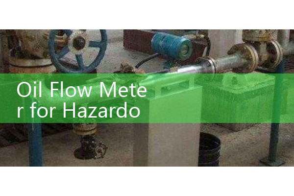
Oil Flow Meter for Hazardous Area: Class 1 Div 1 System Grounding Guidelines
Quick Answer: Proper grounding is mandatory for any oil flow meter installed in a Class 1 Division 1 area. It prevents static electricity from building up on the meter body or rotor and causing a spark. Silver Automation Instruments builds oval gear and Coriolis flow meters with integrated grounding lugs and offers optional grounding rings to meet NEC and API requirements.
Why a Simple Ground Wire Is Not Enough
In Class 1 Div 1 locations, flammable oil vapors are present under normal operating conditions. A single ground wire clamped to a painted pipe might show continuity but still have high impedance at radio frequencies. Real static discharges happen in nanoseconds. So the grounding path must have low DC resistance, typically below 1 ohm, and low impedance at high frequency. Most engineers overlook the paint layer under the clamp. We have measured 50 ohms on a painted pipe that looked grounded.
Standards That Define Grounding for Oil Flow Meters
NFPA 70 (NEC) Article 501 calls for bonding and grounding of all non-current-carrying metallic parts. API RP 2003 covers protection against ignitions caused by static electricity. ISA RP12.6 recommends intrinsically safe wiring practices for field instruments. When you order a flow meter for a Class 1 Div 1 ethanol or crude oil application, the documentation must mention compliance with these codes. Silver Instruments provides declaration letters and wiring diagrams that show the dedicated ground terminal and the path to the plant earth grid.
Practical Grounding Methods for Oval Gear and Coriolis Meters
For an oval gear flow meter, the rotor spins on a shaft that is isolated by bearings. Oil flow can generate static charge even if the fluid is conductive. Our SIL-OG series includes a secondary grounding brush or a grounding ring option. The grounding ring is a stainless steel plate with a threaded terminal, sandwiched between the meter flange and the process pipe flange. It bonds the pipe on both sides to the meter body. A 4 mm² copper conductor from that terminal to the plant ground bus completes the circuit.
With a Coriolis mass flow meter, the vibrating tubes are already connected to the meter case via the driver and sensor coils. But you still need to bond the meter case to the pipe flange. We recommend a braided copper strap across each flange joint if the gasket is non-conductive. A plant in Vietnam processing bunker fuel found that omitting this strap caused a floating voltage of 15 volts on the meter housing. After installing the strap, voltage dropped to zero.
Customer Site Lessons from Southeast Asia and the Middle East
Last year, a palm oil refinery in Sumatra replaced a mechanical meter with an electronic oval gear meter from Silver Instruments. The electrical contractor grounded the meter through the process pipe only. The transmitter showed erratic readings of 30 L/min swings. Our engineer asked for a photo of the grounding connection. The clamp was on a painted reducer. After scraping the paint a
In the Middle East, a fuel terminal in Dubai uses our Coriolis meters for marine diesel custody transfer. They operate in a Class 1 Div 1 area with high humidity. Corrosion on the ground lug increased resistance to 8 ohms over two years. The simple preventive measure is a joint compound applied during installation and an annual loop test. We ship every flow meter with a grounding lug made of 316 stainless steel. The lug accepts ring terminals up to 6 mm².
Silver Automation Instruments Flow Meters for Hazardous Oil Applications
We offer oval gear meters from DN15 to DN100, suitable for diesel, crude oil, lubricants, and heavy fuel. All meters can be certified for Class I Division 1 Groups C and D T4. The SIL-OG model comes with a dual-channel 4-20 mA HART output, PT100 temperature compensation, and an LCD display. Grounding hardware is included as standard. For larger lines up to DN200, our Coriolis mass flow meters provide multi-variable output (mass, density, temperature). The sensor is certified Ex d or IS for hazardous zones. Both designs have been tested for static dissipation per IEC 60079-0.
Send us your pipe size (DN), oil viscosity in cP, flow range, and area classification. We will reply with a grounded flow meter proposal and wiring schematic within one business day.
FAQ
1. Can I rely on the process pipe flange for grounding?
In theory yes, if the flange bolts are conductive and the gasket is a spiral wound type with metal windings. In practice, many gaskets are non-conductive, and corrosion creates high resistance. The safest approach is a separate bonding conductor from the meter ground lug to the plant earth grid.
2. What ground resistance value is acceptable?
The target is below 1 ohm DC resistance measured from the flow meter body to the main earth bar. Some standards allow up to 10 ohms for safety, but for static dissipation the lower the better. We recommend a maximum of 1 ohm for custody transfer systems.
3. Does a battery-powered magnetic flowmeter need grounding in oil service?
Magnetic flowmeters are typically for conductive fluids, not oil. For oil, you need a positive displacement or Coriolis meter. These electronic meters still need grounding even if battery powered, because the electronic enclosure can accumulate static from wind or dust if the area is hazardous.
4. What is the difference between Class 1 Div 1 grounding and ATEX/IECEx grounding?
The physics are identical. NEC (Division system) and IEC (Zone system) both require equipotential bonding. Our meters carry dual certification for both systems. The grounding connection point is the same terminal.
5. How do I verify the grounding after installation?
Use a milliohm meter or a four-wire earth tester. Measure between the meter ground lug and the known ground grid. Record the value and include it in the loop folder. Re-test every 12 months or after any pipe modification.
 Hot Blog
 Related AD